20. Engraving Machine
OF AN ENGRAVING MACHINE, For large Patterns.
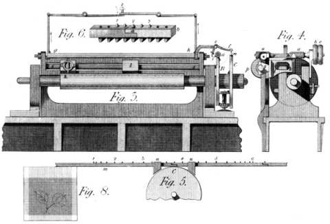
This Machine supposes at once a new kind of engraving, and admits of patterns of very large dimensions. This kind of engraving will be best understood by persons acquainted with figure-weaving; and especially with the manner of mounting the looms for that purpose. In that System, (see Plate 50, fig. 8) the patterns are drawn on ruled paper divided into squares; and each of these squares represents a point in the texture, composed of one or more threads each way; insomuch that whenever that square has any desired colour in it on the pattern, it's threads are taken by the person who prepares the loom; and they are missed in every case where nothing appears in that square, or a colour not then wanted. Now, whatever be the dimensions of these elementary points on the loom, they may be represented by squares of any convenient size on the pattern: only remembering that the smaller they are, in reality, the better will be the delineation. Thus in carpeting, for example, an element of this kind may be a square of one tenth of an inch and more; while one on a ribbon or a piece of silk, is often not the hundredth part. And therefore, the perfection of this engraving depends on the fineness of the points of which the figures are composed. For, in a word, this System proceeds on the same principle. When any part of a line requires a dot or mark to be made, the Machine strikes a blow there; and when no impression is to be made, the Machine (by means that will be shewn) suffers the cylinder to pass that place without striking. The means of regulating this is committed to workmen who merely know how to read off the pattern in it's length, as it is now read off in it's width by the weaver. To describe the construction of the Machine, (as exhibited in figs. 3 and 4 of Plate 50) A is the cylinder to be engraved; and B is a worm-wheel fixed to it's mandril, and destined to turn it. This it does, slowly, by the endless screw a, as turned by proper straps on the fast and loose pullies b c, (figs. 3 and 4). C shews a second wheel, concentric with that B, but running loose on it's axis, which is a pin fitted into the end of the mandril. This wheel, when the threads of the screw a are fine, requires a motion more rapid than the wheel B--to give which motion by means of the latter, we use a pair of multiplying wheels d, which geer, one in the larger bevil wheel cut near the edge of the wheel B; and the other in a smaller bevil wheel cut or fixed on the inner face of the wheel C--and whence this latter wheel receives a velocity of about ten times the speed of B. The use of this wheel C, is to carry, across the Machine, certain bars, of wood or metal, shewn in figs. 5 and 6, whose function is to carry short pins or studs 1, 2, 3, 4, &c. for the purpose of determining the places where the punch is to act, and where it is not. To this end, g h is a frame, which is raised by a cam or tappet i, fixed in the endless screw a, once every turn; and that through the medium of the little tumbler i e f, by which is finally determined whether the stroke shall take place or not--for m being a section of the stud bar of figs. 5 and 6, it's pins, when they occur, raise the end f of the bent lever f e i; and when there is no pin or stud in m, this lever is not raised, and the point i, does not come near enough to the cam to be laid hold of, in which case no stroke is given. This then, is so whenever the studs fail in the bar m; and these fail whenever the pattern-reader has said to the stud-setter, miss; and they occur whenever he has said take--both which cases happen more or less often according to the state of the squares in the pattern.
To be a little more particular: in fig. 5 we see a part of the wheel C of fig. 3, and also a part of the stud bars m m, which geer in the wheel C, and which being conducted by the guides n, follow the motion of that wheel, presenting at f, (fig. 3) a stud to raise the lever f e, whenever the pattern requires it. It may be mentioned, that these studs act obliquely on the wing f of this lever, and thus raise it as they pass under it. And further, these stud bars are made and fitted to each other in the manner shewn at fig. 6. There is a geering tooth under every stud hole, and the last stud hole of a given bar has, fixed in it, a thin tube a, into which the stud enters the same way as in any other place: but this tube whether studded or not serves to lay hold of the succeeding bar b, by it's first hole--so, in fine, as to make the bars endless; the attendant having nothing else to do than to hook them to each other as the wheel C draws them in.
Thus then, are the strokes of the hammer frame, g h, conformed to the pattern: for these bars have been studded before hand by one or more readers and setters; and it is a merely mechanical process to put them in while the Machine moves: from which, by the bye, they fall out after the passage into a proper box, and the studs out of them, to be composed again from the succeeding figures of the pattern. A dozen or two of these bars might be prepared at any time and place, and to any pattern, which they will thus transfer to a cylinder at any desired moment, without the further preparation of dies, punches, mills, &c.--as used in other Machines. N. B. The strength of the blows thus given by the hammer frame g h, is lessened or augmented by the position of the point i fixed to the bent lever i e f, and which makes that lift higher or lower as required--which is a mean of shading offered by this Machine. But to mention it's other properties, the endless screw a, (figs. 3 and 4) carries another endless screw o, more or less fine, which turns at the same time the wheel p, and, by that, the long screw s s, whose office it is to shift, slowly, the punch carriers k l, along the Machine, from k by l, towards s. And here an observation occurs: this can only be so, when the pattern permits the action of the punches k or l, to take place spirally on the cylinder; that is, when the sketches are distinct enough not to shew the anomaly that would occur were a straight pattern thus transferred to a set of spiral lines. But should it be desirable to engrave patterns so correct as to require an exact parallel motion round the cylinder, then the motion of this screw must not be continual--but must intermit and be resumed, at every beginning of a new line round the cylinder. I hope, I make myself understood: a pattern drawn on squares, produces lines all parallel to the first; while the spiral motion of the punch causes a slight deviation--which, in a word, can either be suffered or avoided. At all events, this deviation is so much the smaller as the punch motion is slower in both directions; and, in fine patterns, must be very small. One remark will close this part of the subject: although a fine pattern, requires a great number of blows, and thus a certain expence of time, each blow can be so much the lighter and more frequent; so as to compensate, in some degree, for this cause of delay. I add, that the levers shewn above and around fig. 6, are intended to lift the hammer frame g h, equally at both ends: while the screw Z regulates the depth to which it is permitted to fall.
I observe, finally, that, according to the size of the intended pattern, there are more or fewer of the punch bearers k l, connected, by their nuts, with the screw s s; each of which thus engraves it's sketch, similar to the collateral ones; and that were it wished to make one pattern of the whole length and circumference of the cylinder, a single punch bearer would be required--since nothing else limits the extent of a pattern engraved by this Machine.
Thus have I gone through my proposed "Century of Inventions," for every imperfection in which I beg the indulgence of my numerous readers. And here I can truly say I have neglected nothing--although the precarious state of my health may have sometimes veiled the evidence of my descriptions. On the other hand, I did not even attempt many of the lesser details of execution; as I wrote for those to whom they would have been superfluous: but as to the objects themselves, I believe there is not one that is without the pale of practical utility. In a word, many of the subjects have been frequently executed, and are in daily use; and as to those which remain to be tried, I engage, if called on, to give them useful existence. And the better to convince candid minds of the serious attention I have paid to these subjects, I shall add the scales on which they have been executed, or to which they are drawn--those scales expressed by a fraction, shewing what proportion the figures bear to the reality. Thus the scale of one inch to a foot will be expressed by the fraction 1/12; that of two inches to a foot, by 1/6, &c. that is, the figures, in these cases, will be (nearly) 1/12 or 1/6 of the size of the Machines.