4. Bisecting Compasses
OF THE BISECTING COMPASSES.
It often happens, that from a central line, (in drawing for example) we want to set off, quickly, many equal distances on each side; or between two given lines we want a central line; to perform either of which operations, is the use of the Instrument just mentioned.
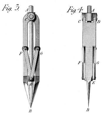
It is represented in Plate 44. figs. 3 and 4, where A B is the central point, being cylindrical in the greatest part of it's length, and conical at E B. It slides correctly in two cannons or swivels E & A, which also have two short axes or trunnions, on which first, the double compass joints C D turn; and second, the two pairs of arms F G. I have called these cannons, swivels, that I may shew their construction, by referring to figure 1 in Plate 30--which describes the swivel of the forcing Machine; and which will give a complete idea of what is here intended. From this construction it will appear evident, that the point A B, (Plate 44) will be always found in the middle, between the two points, of the outer legs of the compasses; and that whether the question is to take two equal distances from a central point, or to bisect a given line or distance at one operation. The point or style now slides in the two swivels A and E; but the Instrument might be so constructed, as for it to follow the rising motion of the middle joint (E), and thus to keep the three joints in the same horizontal line: but I think a small perpendicular motion of the said style, would be always desirable in the Machine, as a drawing Instrument.