3. Description Of Machines
Full descriptions of our various forms of Machine would occupy too much space, and unnecessarily extend the pages of this pamphlet. The idea that seems to be held by many manufacturers of Gas Machines, that one form or style of Machine, varied only in size, is suitable for all kinds of work, is an error to which may be attributed the frequent failures of Gas Machines to produce the expected results. The fact is, that some kinds of work can be more economically and effectually done by modifications and combinations which it would be folly to use for others.
The class of building to be lighted has much to do with the form in which the Machine should be made. The Machine best adapted for a large Mill might be altogether unsuitable for lighting a Church with an equal number of burners; and the surrounding circumstances might require important modifications in a Machine for lighting one Mill or Church which would be perfectly adapted for another of the same size.
For these and many other reasons of a kindred nature, we request that, whenever it is practicable, we may have an opportunity to see the buildings and grounds, or receive otherwise as full information as possible before estimating on work.
Figure 1 illustrates our Machine as usually made and placed for lighting Residences. The Air Pump is shown in cellar of building, operated by means of weight and pulleys attached to ceiling. The Generator is buried in the earth (at any desired distance), and supplied with Gasolene (once in three to six months) through one of the Pipes running to surface of ground. The Generator has from two to ten compartments (as illustrated in Fig. 5), the number of compartments depending upon the number of burners to be lighted. The operation consists in the Air Pump taking common air from outside the building through an Induction Pipe, and forcing it (by means of the weight) through the Syphon Pipe out to the Generator; thence through the meshes of evaporating material in the passages of Generator to the Exit Pipe. By this time the air is thoroughly impregnated with the carbonaceous vapors of the Gasolene, and passes (under the same pressure) through the main Gas Pipe to the house, and thence to the burners. In one of the Pipes running from Generator to surface of ground is a brass rod, attached to a float in Generator, so that the quantity of Gasolene on hand may at any time be ascertained by removing the Cap from top of said Pipe.
Figure 5 represents one of our " Underground" Generators, with the front end and part of the top removed, so that the inside arrangement may be seen. It is divided horizontally into a series of reservoir chambers, varying in depth from four to fourteen inches. These reservoirs or pans are divided into narrow passages, in which are arranged the meshes of Carbureting material. The Gasolene is supplied to the top pan through a pipe running to surface of ground (see Fig. 4), and after rising to the height of overflow tube in upper left hand corner, runs over into the second pan, thence into the next, and so on until all the upper pans are nearly full and the Float Wire (see Fig, 4) indicates that a sufficient quantity is in the bottom pan.
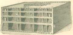 Figure 5 - Underground Generator
It is in this vessel that the Gas is made. The air, entering the right hand passage of lower pan, above the Gasolene level, is forced through all the meshes of Carbureting material in each successive passage of all the pans, thus becoming thoroughly mixed or impregnated with the vapors of the Gasolene before reaching the Gas exit in right hand passage of the top Pan.
We call especial attention to the following peculiar features of our " Underground " Generator.
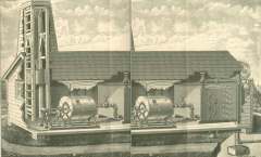 Figure 6. Imperial Gas Machine
First. It will be noticed that the Reservoir Pans are of unequal depth, the deepest being at the bottom and the shallowest at the top. The object of this is to insure a uniform consumption of the Gasolene. The air from Air Pump enters the bottom pan and passes out the top pan. . In any Generator, made with a series of Reservoir Pans, one above the other, the quantity of Gasolene taken from the several Pans will be in proportion to their proximity to the air entrance, the greatest quantity being taken from the bottom Pan and the least quantity from the top Pan.
The advantage of our arrangement is obvious. So long as any Gasolene remains in the Generator it is equally distributed in the several pans, thus ensuring greater efficiency than if the pans were of equal depth, in which case the lower pans would be empty (and of no value) long before the upper pans.
Second. It will be noticed that our Generator is square. The advantage of this is strength. In all Pan Generators the passages are made of wood. In a round Generator the wood-work adds no strength to the sides thereof. In a square Generator, the sides as well as the top and bottom are lined with wood-work, which, braced by the partitions, makes a most substantial machine.
Third. Our Generator is made to bury in the ground. It has no valves or other movable parts except the float for indicating the quantity of Gasolene.
Fourth. It is not simply a Reservoir. Every inch of space is filled with Carbureting material, the exposure of which is increased as the Gasolene is used, thereby securing a more even quality of gas than with any other Generator yet produced.
A practical advantage resulting from the above mentioned "special features " of our Generator is that, unless they are used far beyond their rated capacity, there is no residuum - all the Gasolene is used up.
Figure 6 illustrates our Machine as frequently placed for large work. The entire Machine is placed in a Gas House, which may be located at any convenient point on the premises, and the Main Gas Pipe run in any direction to the building or buildings to be lighted.
The Gas House is usually built with a Tower, as shown, for the purpose of providing a sufficient " fall" for the Weight. The Air Pump is shown with Compound Gear, but whenever a supply of Water can be obtained, the Tower, Compound Gear, Weight and Pulleys may be dispensed with and the Water Motor used, as shown in Fig. 7.
The Generator shown in Fig. 6 is designated the "Overflow-Pan" Generator, while those shown in Figs. 1, 4 and 5 are styled " Underground" Generators. The distinguishing feature of the "Overflow-Pan" Generator consists in an arrangement of overflow Cocks, by means of which the Gasolene maybe transferred from the upper to the lower pans before each filling, thus compelling the Air from Air Pump to operate first upon the older Gasolene in lower pans and then upon the fresh Gasolene in the upper pans.
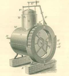 Figure 7. - Imperial Air Pump With Water Motor
We make the "Overflow-Pan" Generator to supply from two hundred burners up. They cost about 10 per cent, more than the "Underground" Generator, but in many cases, where a large quantity of Gas is to be used, the advantages gained will more than compensate for the slight additional cost.
Another way of placing this style of Generator is shown in Figure 8, which illustrates the " Overflow-Pan " Generator partly buried in the earth, one end of it projecting into a vault. When the Generator is thus placed the Air Pump may be located at any convenient point in the building lighted or in an out-building.
The " Over-flow Pan " Generator is peculiarly adapted for the use of steam, when it may conveniently be had, for re-supplying the heat taken off by the process of evaporation.
Figure 7 is an illustration of our Air Pump so arranged as to be operated by an overshot Water Wheel, the usual running Gear, with Weight and Pulleys, as shown in other illustrations, being dispensed with.
The Water Wheel, "S," is fastened to shaft of Air Pump. The Valve, " R," is connected with a water supply pipe, and, when open, admits the water through Pipe, " R-," to the buckets of Wheel. The weight of water is sufficient to operate the Air Pump, which discharges its air into the Ometer, " P." As the Ometer rises, the Valve, " R," is closed by means of Lever, " R 1 " thus stopping the flow of water. The usual pipe connections being made between Outlet " H " and the Generator, and thence to the Gas Pipes in building, the pressure in Ometer, " P," is communicated to the Generator and all connecting pipes, and the Ometer will remain elevated until the pressure is reduced by turning on the lights. Then, as the Ometer falls, the Water Valve is opened (by Lever " R 1 "), and just enough water is supplied to the Wheel, " S," to maintain the pressure for the number of burners that are lighted. When all the burners are closed, the Ometer again rises and cuts off the supply of Water.
After the water has done its work, it is discharged through Waste Pipe, " T1, " and may be used for Laundry or other purposes.
This attachment is perfectly automatic in its operation ; requires no attention ; it is thoroughly effective and reliable.